
Cam Followers
Cam Follower Series
We manufacture our KIS cam followers in the following designs:
Cam followers without eccentric collar
Cam followers with eccentric collar
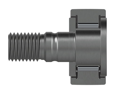
T-shaped thrust washer seal (KR…PP)
or
open (KR…)
+ cage
T-shaped thrust washer seal (KRE…PP)
or
open (KRE…)
+ cage
T-shaped thrust washer seal (KRV…PP)
or
open (KRV…)
full complement needles
T-shaped thrust washer seal (KRVE…PP)
or
open (KRVE…)
full complement needles
Labyrinth seal (NUKR…)
full complement rollers
Labyrinth seal (NUKRE…)
full complement rollers
Protected lip seal (PWKR…2RS)
full complement rollers
with centre rib
Protected lip seal (PWKRE…2RS)
full complement rollers
with centre rib
Cam Follower Series
Customer-specific system or component solutions are our core competence at KIS. As an experienced rolling bearing manufacturer, we focus our developments on rolling bearings and slewing rings. We develop complete solutions for you based on our own KIS products and combine them with our comprehensive all-round service for drive technology. Whether it is the careful selection of individual components or the proper assembly that ensures the flawless function of the system solution: as bearing specialists and a reliable rolling bearing manufacturer, we take on every process step – from development and design, through monitoring of production and assembly, to extensive quality inspections and field tests.
- Special dimensions
- Optimised internal design (especially for applications with high radial loads)
- Application-specific material solutions, surface treatments and coating variants
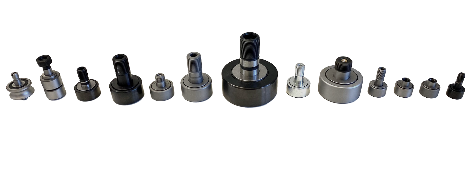
Cam Follower Profiling & Misalignment
Profiling & design of the outer ring outside surface
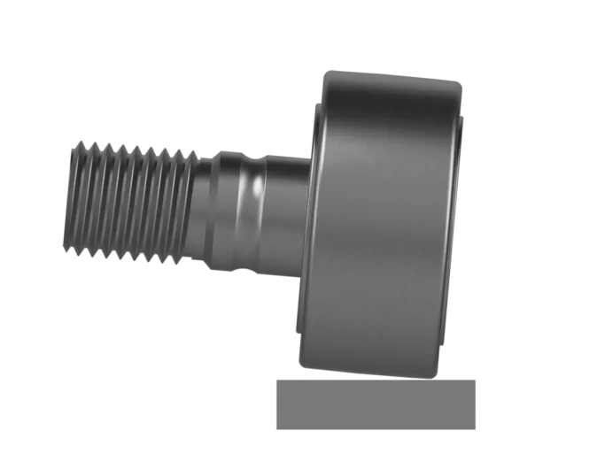
In cam followers there is line contact between the rolling elements and the raceway, as well as between the crowned outer ring surface and the mating track.
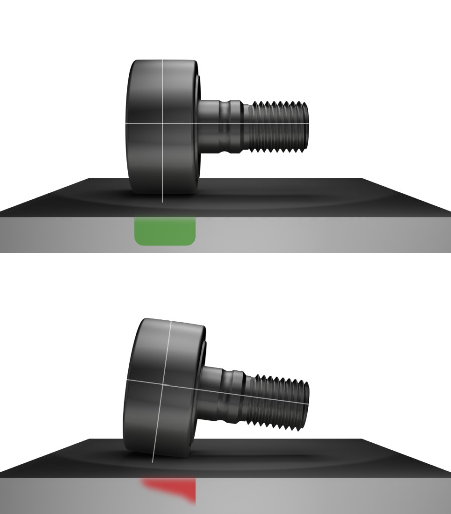
Cam followers are generally shaped so that they sit optimally on the guide rail. For this purpose they have a rounded surface (spherical outside surface) along their longitudinal axis. This is important because the cam follower and the guide rail are not always perfectly aligned, which can lead to a skewed position. The rounded shape of the roller distributes the pressure better and no sharp pressure points or wear occur at the edges (edge loading).
However, this also reduces the contact area between the roller and the guide rail. To compensate for the resulting higher pressures, the guide rail must be designed more robustly.
The KR…PP, KRV…PP, NUKR, NUKRE, PWKR…2RS and PWKRE…2RS series have an optimised crowning radius of R=500 mm as standard. The distribution and the maximum value of the local contact pressures are decisively influenced by the extended modification of different profiles. With lower degrees of profiling, the pressure distribution becomes more uniform, but this results in increased edge stresses, particularly at higher tilt angles.
Depending on the application, this offers the following advantages, among others:
- Avoidance of edge loading, especially under misalignment
- Reduced Hertzian contact pressure
- Higher basic rating life of outer ring and mating track
- Reduced wear and reduced pitting in the tribological system
- Positive influence on the ratio of applied load to radial deflection (stiffness)
- Significantly lower coefficient of friction at low and high relative speeds
- Faster transition into the fluid-friction regime to achieve maximum service life
If required, our cam followers can also be produced with a cylindrical outside surface, e.g. for applications that demand high stiffness and in which no errors with regard to skewing and misalignment occur.
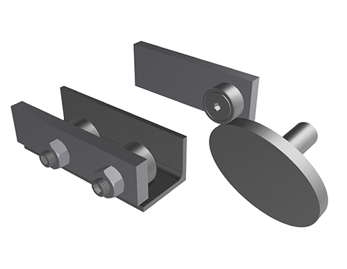
Origin of axial loads
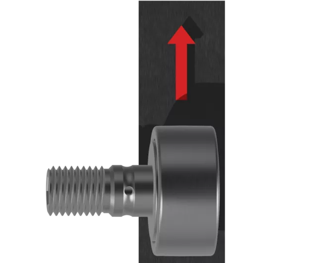
It can be assumed that the outer ring of the cam follower is not axially clamped. In an atypical application, the cam follower runs on a track parallel to its axis and its surface can only absorb radial forces. Under these conditions, axial loads are generated by misalignment, either because the axis of the cam follower is not parallel to the track or because the axis of the cam follower is not perpendicular to the direction of movement – a combination of both cases is of course also possible.
Misalignment
In general, misalignment reduces service life and must therefore be kept to a minimum by means of suitable adjacent constructions.
With cam followers with a cylindrical outer ring, particularly high edge stresses occur between the outer ring and the mating track when running misaligned. Due to their rolling elements with line contact (needles or cylinders), cam followers are generally less able to absorb the axial forces resulting from this positioning error than, for example, track rollers with balls. A spherical or crowned outer ring profile reduces this sensitivity.
The following guide values can be regarded as the limit of the tilt angle:
Cylindrical profile > 0.1°
Spherical profile > 0.25°
In the figure, the axis of the stud is inclined relative to the track. The magnitude of the axial load is a function of the tilt angle and is usually quite small. At best, the outer ring rests on the track over its entire length and the misalignment occurs internally as long as the angle lies within the diametral bearing clearance. The misalignment becomes immediately apparent when the contact surface on the outer ring is examined after a short period of operation. This condition leads to an internal roller pressure load, which can be compensated by using a crowned outer ring. Since cam followers are cantilevered devices, an offset occurs when the stud deflects under load. Misalignment is therefore unavoidable, shortens the service life of cam followers and impairs the sealing capability. Cam followers have been further developed to optimise this condition by providing greater roller end support. This improves the ability to absorb and accommodate the resulting axial forces.
Predominantly radial loads
Thanks to their thick-walled outer rings, cam followers can absorb high radial loads. With axial guidance provided by the retaining flanges of the stud and the pressed-on end washer, these bearing designs tolerate axial loads. The magnitude of the permissible load is determined by the internal design.
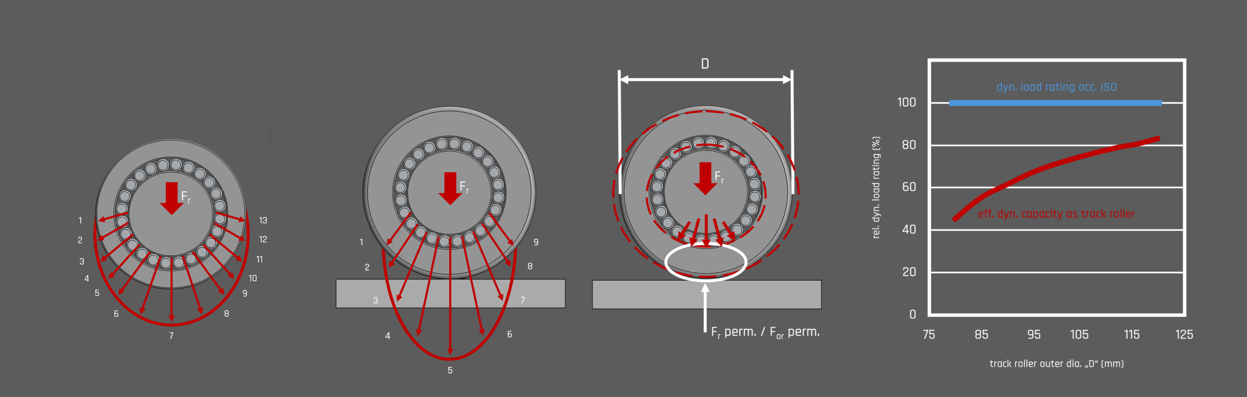
Load ratings
When a cam follower runs on a straight or curved mating track, the contact under radial load causes an elastic (oval) deformation of the outer ring. For this reason, these bearing types have an outer ring with an enlarged cross-section compared to standard bearings, where the forces are transmitted via the outer ring directly into the housing (without significant deformation). This enables the outer ring to absorb increased bending stresses and the associated deformations.
However, the deformation means that a smaller area of the raceway is loaded (reduced contact zone) and the load is thus distributed over fewer rolling elements, which in turn affects the dynamic and static load ratings.
The load ratings Crw and C0r w are decisive for the rating life calculation. For a rating life calculation according to DIN ISO 281, the following applies:
C0r w = C0r
Cr w = Cr
The permissible effective radial loads Fr and F0r take bending stresses in the outer ring into account. The bending stresses must not exceed the permissible strength values of the material. If the data sheets do not contain values for Fr and F0r, the following applies:
F0r = C0r w
Fr = Cr w
Radial load under dynamic loading
The dynamic load rating denotes the radial load at which 90 % of a group of identical cam followers can perform 1 million revolutions without material damage due to fatigue in the rolling contact.
The elastic deformation of the outer ring affects the load distribution between the rolling elements and reduces the load calculated according to the ISO standards for bearings. The effective dynamic load rating Cr w applies to dynamically loaded rotating bearings. The basic rating life is to be calculated with Cr w. The permissible dynamic radial load Fr must not be exceeded. If Fr is not specified, the effective dynamic load rating Cr w applies instead. This must likewise not be exceeded by the actual radial load. If the static load rating C0r w is lower than the dynamic load rating Cr w, then Cr w applies.
Radial load under static loading
The static load rating denotes a static radial load at the centre of the contact area between rolling element and raceway under the highest possible load, with respect to the plastic deformation of the cam follower.
For statically loaded bearings, at standstill or with rarely occurring rotary movements, the effective load rating C0r w applies. The static load safety factor is to be calculated with C0r w.
This is contrasted by the permissible static radial load F0r, which must not be exceeded. If F0r is not specified, the effective static load rating C0r w applies instead. The smaller value in each case applies as the permissible maximum load. In some applications, the permissible load of cam followers is limited by the bending and shear strength of the stud and the strength of the outer ring, and not by the load rating of the needle or cylindrical roller bearing. The maximum permissible static load limited by these strengths is therefore specified.
In addition to the permissible radial load of the bearing, the permissible radial load of the mating track must also be observed.
Minimum load
Like all rolling bearings, cam followers are also subject to a minimum load. If this is not reached, the rolling elements cannot roll properly. This increases the risk of sliding friction. Sliding breaks through the lubricant film in the contact zone and leads to metal-to-metal contact, which causes both friction and adhesive wear (smearing) to rise sharply. The minimum load is an important parameter, particularly for cam followers, which are often exposed to rapid start-stop loads or high accelerations. If these requirements cannot be met, DLC coatings, application-specific lubrication concepts or cam followers of a smaller dimension series should be considered.
Angular misalignment
The figure shows the misalignment in which the axis of the cam follower is not perpendicular to the direction of movement. In this case, the outer ring wants to roll out of the centre of the mating track but is prevented from doing so by the adjacent construction or the axial fastening. This results in a simultaneous rolling and sliding motion and thus axial slip in the rolling contact between the outer ring and the mating track.
The axial load generated by the sliding motion is the radial load multiplied by the coefficient of friction between the outer ring and the mating track. Note that the alignment error does not enter into this equation, so the magnitude of the axial force is independent of the angle. To minimise wear in the tribological system due to angular misalignment, it is essential that the mating track is properly lubricated in order to keep the coefficient of friction as low as possible.
Severe wear of the contact surfaces and, as a consequence, a complete loss of static friction between the outer ring and the mating track must be expected at the following skew angle:
Skew angle ≧ 1.4 · 10 –4 · pH (°)
or
Skew angle ≧ 2.5 · 10 –3 · pH (mrad)
Limits of axial loading
In general, cam followers with cylindrical rollers can absorb higher axial loads than needle-bearing cam followers and therefore have a longer service life under such conditions. A rolling element is referred to as a cylinder if its length is approximately equal to or less than its diameter. For needles, the ratio is significantly larger, often greater than 4. These values may vary depending on the specific application and manufacture, but provide a general guideline for distinguishing between them.
However, there are some practical limitations, such as the ratio of radial to axial load. In dynamic applications, the axial force should not exceed 10 % of the applied radial force. In static applications, this ratio can be up to 20 %.
Lubrication
Two tribological systems – and thus two contact conditions – must always be evaluated separately:
- The rolling elements and the rolling element raceway
- The outside surface of the outer ring and the mating track
Depending on the design, cam followers offer relubrication options via the bearing stud. In series with an eccentric collar, the eccentric ring covers the radial lubrication hole of the stud. Relubrication must therefore be carried out via the end faces.
The following conditions influence the relubrication intervals:
- Loads
- Speeds
- Frequency of direction changes
- Contamination or cleanliness of the environment
- Temperatures (shorter relubrication intervals from 70 °C)
- Internal geometry
- Cage or full complement rollers/needles (→ shorter relubrication intervals)
Lubrication of the rolling elements and the rolling element raceway
The maximum amount of grease a bearing can hold is a function of the free space available inside the bearing. This means the volume created between the outer rolling element raceway and the inner rolling element raceway, minus the volume of the rolling elements and the additional space that may be present due to sealing concepts, two rolling element raceways, etc. Ideally, relubrication should be carried out regularly, even if the initial fill still has full lubricating properties.
In cam followers with needles, the large number of needles takes up most of the available space, leaving little room for lubricant. It primarily fills the cavity between adjacent rolling elements and the inner or outer raceway. The main cause of premature wear is a lack of lubricant. The larger the grease fill, the longer the product lasts in most common applications. As a protective function, excess grease is carried outwards by centrifugal force and with the help of the sealing lip structure (including the groove geometry).
In cam followers with cylinders as rolling elements, the cavities between the rollers and the raceways are larger, although there are fewer of them. However, additional space for lubricant is available in the area between the roller pairs and between rollers and seals. As a result, cam followers of the same size contain up to four times more grease than cam followers with needles.
For KIS cam followers, an EP-additivated, fully synthetic high-performance grease (consistency class NLGI 2) is used as standard, which was specially developed for use in applications with high radial loads (including heavily oscillating operation). It combines the advantages of a synthetic base oil and a special lithium complex thickener with those of a state-of-the-art additive package.
Thanks to its wide temperature range, high mechanical stability and exceptional load-carrying capacity, it is an excellent choice. The effort required for a reliable grease supply is considerably reduced by using this product. The lubricant can be used with grease guns, automatic relubrication systems and centralised lubrication systems.
Lubrication of the cam follower outside surface and the mating track
All lubricants suitable for rolling bearing lubrication can be used to lubricate the mating track. However, there are also applications in which the mating track must remain unlubricated. If lubrication is not possible, wear must be expected, particularly under high loads and high alternating speeds. In these cases, please feel free to contact our technical support.
Relubrication intervals can only be determined under operating conditions – at the latest, however, when the first signs of tribocorrosion become visible in the tribological system.
Properties

Sealing variants and axial guidance of the outer ring
Our product portfolio covers open and double-sealed variants. Depending on the series, low-contact T-shaped thrust washer seals or contact-type labyrinth seals and protected lip seals seal the internal system.
Properties of the sealing variants:
Seals protect the tribological system of the bearings against loss of lubricant, prevent the ingress of contaminants and guarantee relatively low-friction operation.
There are further design differences between cam followers with cylinders and those with needles as rolling elements. One of the most important is the axial guidance of the outer ring. The outer ring is guided between the two flanges and rubs against one or both flanges under axial load. To prevent direct metal contact between the outer ring faces and the retaining flanges of the stud and the end washer, the T-shaped thrust washer seal usually has a radial extension that reaches into the gap between the outer ring and the flange or end washer. The radial extension thus acts as a plastic thrust washer. To fulfil this function, the seal material must have good load-bearing capacity and be sufficiently stiff for the application.
These requirements call for material properties that contrast with those of conventional seal materials, where the flexibility and conformity of the sealing lips are the focus. Consequently, T-shaped thrust washer seals are gap seals that rely on a lubricant barrier as their sealing function and therefore on relubrication. During running-in, centrifugal force carries excess grease into the gap seals. At constant speed, this inflow stops until the next relubrication cycle.
It must be ensured, however, that the axial loads on the radial extension of the T-shaped thrust washer seal are not too high, in order to avoid steel-on-steel contact in which abrasive and/or adhesive wear on the contact surfaces would negatively affect service life. With cylinders as rolling elements, the end faces act as guidance for the outer ring. Although this is again a steel-on-steel sliding contact with comparable loads, this condition is optimised by the simpler lubrication conditions. The rolling motion of the cylinders transports fresh lubricant into the contact zone with every revolution. The shoulders with the undercuts at both ends of the outer ring, together with the lip seals, prevent lubricant from escaping.
Speeds
The permissible speeds given on the data sheets are empirical values. They are not universally exact values and may deviate downwards or upwards under real conditions depending on the operating conditions of the rotary solution, and may therefore be modified.
As speed increases, the bearing temperature also rises due to heat generation at the contact surfaces between cage, raceways and rolling elements, until increased wear in the tribological system can eventually occur. It is therefore necessary to keep the speed of a bearing below a certain limit value in order to ensure safe operation over a long period. Since the heat generated is roughly proportional to the sliding speed at the contact surface, this sliding speed is an indicator that defines the limit of the permissible speed.
- Speed limits (including the associated permissible operating temperature) depend largely, but not exclusively, on the following factors:
- Rolling element guidance (especially on entering the load zone)
- Lubrication
- Bearing type
- Main loads
- Cooling conditions
- Seal
- Intermittent or continuous operation
- Radial clearance
- Mating track (including lubrication)
End face guidance requires a length-to-diameter ratio of the rolling elements of 2.8 or less so that optimised alignment on entering the load zone can be guaranteed. Needles, on the other hand, have a far greater ratio and can neither be guided at the end faces nor absorb axial loads. They rely on the crowned outer ring surface to correct misalignment. This means that cam followers with cylinders as rolling elements can operate at higher speed ranges, whereas needles exhibit small misalignments on entering the load zone, which leads to sliding movements and promotes heat generation.
Operating speed
The permissible speeds given on the data sheets are empirical values. They are not universally exact values and may deviate downwards or upwards under real conditions depending on the operating conditions and application of the rotary solution, and may therefore be modified.
Speed adjustment
Speeds must be reduced or determined more precisely in the case of:
- Loads > 0.05 * C0r w
- Bearing variants with needles as rolling elements
- Difficult lubrication conditions (including mating track)
- High sealing requirements (higher contact friction)
- Tight radial clearance tolerances
- Additional axial loads
- Insufficient heat dissipation
- Need for a high-viscosity lubricant
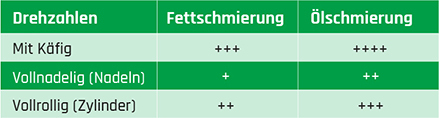
Speed increase
Oil-lubricated cam followers can generally be operated at a 50 % higher speed than grease-lubricated solutions, although rolling element guidance has a much stronger influence on the maximum speed. Intermittent operation can also raise this value further.
With a sealed cam follower with cylinders, the speed is limited by the maximum permissible surface speed of the seal.
Cage-guided (usually plastic) rolling elements also reduce internal friction and provide a larger lubricant reservoir than full complement roller (or needle) variants. However, lower load ratings must then be taken into account, as fewer and shorter rolling elements are used due to the cage volume.
Temperature ranges
The maximum values shown in the following table are only permissible for short periods. If values are permanently elevated, an application-specific analysis is essential.
Dimensions & Tolerances
The dimensional and running tolerances correspond to tolerance class Normal according to ISO 492; for KR, KRE and KRV according to ISO 7063.
Possible deviations from ISO 492 can be found in the individual KIS technical data sheets.
Tolerances for coated bearings
For coated cam followers, the tolerances increase by the layer thickness of the selected special coating.
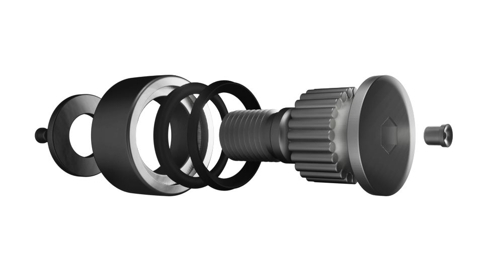
Bearing clearance
Cam followers are designed with a tighter radial clearance in order to extend the load zone. The standard is approximately C2 (Group 2) or CN.
The values for radial internal clearance correspond to DIN 620-4:2004 (ISO 5753-1:2009) and apply to cam followers in the unloaded state, free of measuring force (without elastic deformation).
Radial internal clearance for support rollers and cam followers
Speeds
Rating life calculation
Possible methods for the rating life calculation are the basic and modified basic rating life calculation according to DIN ISO 281 and the extended calculation of the modified reference rating life according to DIN ISO 281-4.
The basic rating life is the number of revolutions that 90 % of a sufficiently large group of identical bearings will reach or exceed at constant load and speed before the first signs of material fatigue occur.
Use effective dynamic/static load ratings
These methods are described under load-carrying capacity and rating life. For support rollers and cam followers, the following values are used:
- for Cr the effective dynamic load rating Cr w
- for C0r the effective static load rating C0r w
- for Cur the effective fatigue limit load Cur w
Service life – actual life achieved
The service life is the actual life achieved by a support roller, cam follower or track roller and can deviate significantly from the calculated basic rating life.
Service life – causes of deviations
Deviations between basic rating life and service life result from wear or fatigue due to:
- Misalignment between track roller and mating track
- Deviating operating data
- Operating clearance too small or too large
- Very high shock loads, static overload
- Contamination of the track roller
- Excessive operating temperature
- Insufficient lubrication
- Oscillating bearing movement with very small swivel angles, causing false brinelling
- Wear between the outer ring outside surface and the mating track
- Vibration loads and false brinelling
- Pre-damage during mounting
Due to the variety of installation and operating conditions, the service life cannot be calculated precisely in advance and can most reliably be estimated by comparison with similar installation cases.
Adjacent construction for cam followers
Bore tolerance H7: results in a clearance fit, since the tolerance of the stud diameter is h7 without eccentric collar and h9 with eccentric collar
- Lead-in chamfer on the locating bore: maximum 0.5×45°
- The contact surfaces for the cam followers must be flat, square and sufficiently high. The strength of the nut contact surface must be sufficiently high.
- Cam followers must be axially secured with a hexagon nut. These are not part of the standard scope of delivery and must be ordered separately or noted on the respective data sheet. The strength and roughness of the nut contact surface must be selected so that settling effects do not lead to a loss of preload force.
- For highly loaded applications or strong vibrations, special fastening variants (e.g. self-locking nuts) or an interference fit with stud diameter h7 must be selected.
- The position of the radial lubrication hole is marked on the end face of the roller stud. It must not lie in the loaded zone and should not be positioned 180° from the most heavily loaded zone in order to ensure an adequate lubricant supply.
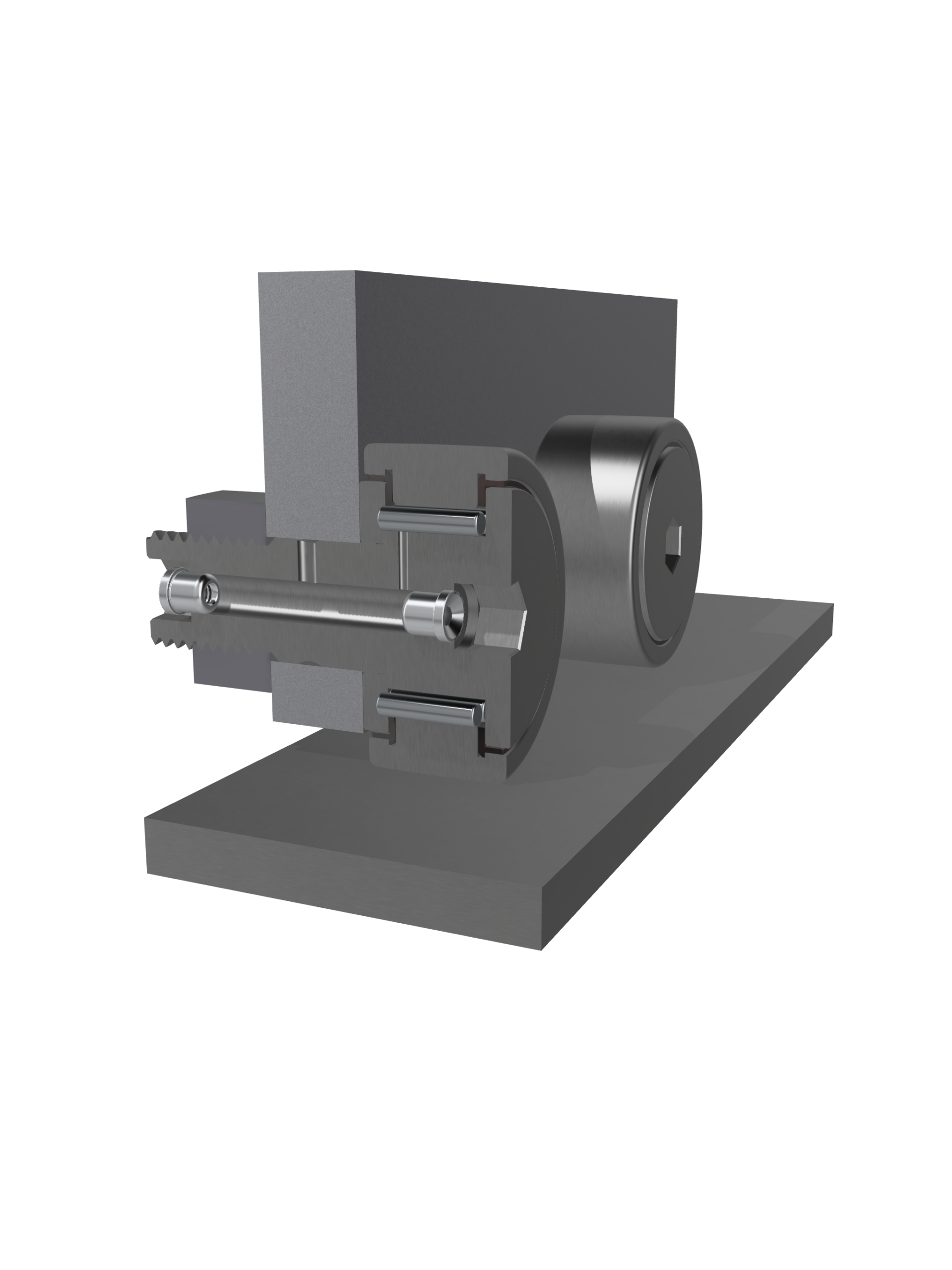
Mounting
Mounting
Great care must be taken when mounting cam followers to ensure trouble-free operation:
- Cam followers must be protected against dust, dirt and moisture. Contamination can lead to increased wear and premature failure
- Do not overcool cam followers. Condensation may lead to corrosion in the bearings and bearing seats
- Keep the assembly area dust-free and clean
- Check the axle seat for dimensional, geometric and positional accuracy and cleanliness
- Lightly oil the seating surfaces of the bearing rings or rub them with solid lubricant
- Supply the bearing with lubricant after mounting
- Final functional check of the bearing arrangement
Mounting tools
Depending on the application, the following tools are suitable:
- Induction heating devices, observing the manufacturer’s instructions regarding seal and lubricant
- Heating cabinets with heating up to +80 °C
- Mechanical or hydraulic presses: use mounting sleeves that bear against the entire circumference of the bearing ring end faces
- Hammer and mounting sleeves: strike the sleeve centrally
Important when mounting
With cam followers with an eccentric collar, the fitter can adjust the radial position of the bearing relative to its support housing. This is particularly useful when several cam follower bearings carry a load and mounting inaccuracies prevent the standard bearings from distributing the load evenly. The eccentric adjustment can also reduce wear of the tracks.
- Do not transmit mounting forces through the rolling elements
- Do not damage the seals
- No blows to the bearing rings
Dismounting
The possibility of dismounting should already be considered when designing the bearing position. For reuse:
- Avoid direct blows to the bearing rings
- Avoid dismounting forces through the rolling elements
- Only clean bearings in the dismounted state
- No hard flame
Mounting press for mounting and dismounting
- Mount cam followers with a mounting press wherever possible, as shown in the figure
- No blows to the thrust collar of the roller stud
- The lubrication hole must not lie in the loaded zone and is marked on the collar side of the roller stud.
Drive-in grease nipples for cam followers
- Fit grease nipples before mounting the bearings
- Drive-in grease nipples are supplied with the cam followers. These must be properly pressed in before the bearings are mounted. Only the supplied grease nipples may be used.
- For lubricating the cam followers with the centralised lubrication adapter.
- If lubrication is carried out via the locating bore, the axial lubrication holes in the cam follower must be closed with the grease nipples before mounting.
Axial fastening of cam followers
Cam followers must be axially secured with a hexagon nut. The slot or hexagon at the end of the roller stud allows the bearing to be held with a spanner while tightening the fastening nut and the eccentric collar to be adjusted. In the case of strong vibrations, special serrated lock washers or self-locking nuts according to DIN 985 can also be used.
Axial fastening – important to note:
The tightening torque of the fastening nuts must be strictly observed in order to guarantee the permissible radial load. If it cannot be observed, an interference fit is required. With self-locking nuts, an increased tightening torque and the instructions of the nut manufacturer must be observed.
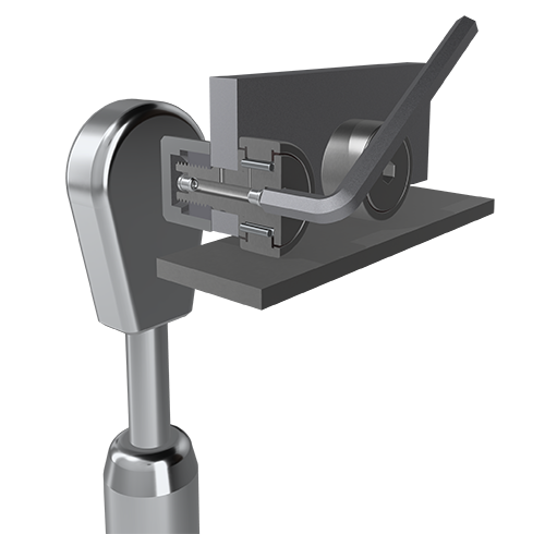
Cam followers with eccentric collar
The highest point of the eccentric collar is marked on the roller stud side, where the radial lubrication hole is also located.
Commissioning and relubrication
Cam followers each have a lubrication hole for relubrication:
- on the collar side of the roller stud
- on the end face on the thread side, from an outside diameter of 22 mm
- on the shank of the roller stud, from an outside diameter of 30 mm with an additional lubrication groove
Commissioning and relubrication – important to note:
- Cam followers with an eccentric collar cannot be relubricated via the shank, as the eccentric ring covers the lubrication hole.
- For lubrication, only use grease guns with pointed needle nozzles that have an opening angle of 60°.
- Before commissioning, the lubrication holes and supply lines must be filled with grease for corrosion protection reasons; lubrication can be carried out at the same time.
- Lubrication is made more difficult if a rolling element is positioned over the radial lubrication hole. Relubrication should therefore be carried out while the bearing is warm from operation and rotating, as well as before standstill and before longer interruptions in operation.
- The same lubricant as used for initial lubrication must be used for relubrication. If this is not possible, the miscibility and compatibility of the lubricants must be checked. Relubricate until a fresh collar of grease forms at the seal gaps. The old lubricant must be able to escape freely from the bearing.